- +91-9971077233, +91-9821041467
- labequipments.in@gmail.com
- ENG
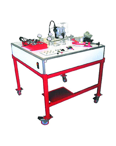
The trainer should be designed to demonstrate the theory and operating characteristics of todays modern braking systems, ABS system of various types are being included on newer vehicles as it greatly improves the control of the driver during braking, which feature computer controlled anti-locking or skid-control systems. The unit should consist of original automotive ABS braking components, which should be mounted onto an integrated floor stand, made from powder coated electro galvanized steel, that are mounted onto wheels for mobility. A color coded schematic chart, under a lexon polycarbonate protective screen, of the ABS system and circuit’s, should also be mounted onto the trainer for reference.
Specifications:
1. The trainer should consist of a complete, fully operational, ABS unit which is typically found on passenger vehicles. The trainer should have the following specifications:
Four rotating wheels with wheel sensors
Four variable speed electrical drive system for each wheel to control the individual speed of each wheel
Master brake cylinder with pedal handle
ABS hydraulic actuator (modulator) unit which is controlled by the on-board computer system (ECU)
Five brake line pressure gauge to show the pressure differentials from the meter brake cylinder to the individual wheels
Brake master cylinder with vacuum assist boost mechanism and brake pedal assembly.
The front of the trainer features precise schematic color graphic illustrations that clearly explain the operation of the entire ABS and braking system.
A control Panel should be provided with an on/off power switch, power system light (POWER ON), ABS warning light (indicated problems) and an ABS operational light (ABS ON). Also has Volt and Ampere meters to measure the DC input power and a brake light to show the operation of the braking system just as on the vehicle.
Road Conditions and Performance Display Panel.
The trainer should come complete with a training course on ABS operation and servicing including student job sheets and a technical manual on ABS systems
2. Modules:
The trainer should be developed not only to be just a simulator but the ABS system is fully functional, featuring a real ABS unit and real brake systems which makes it ideal for student observation, experimentation and also trouble shooting.
Different friction values could be set for each wheel to simulate variable road conditions.
Control of the braking action could be observed with either the ABS unit on or off.
ABS unit should be clearly laid out on a display board that is mounted on a mobile trolley.
3. Electronic/Electrical Fault Insertion System:
Multiple electronic fault insertion system: This system should allow for up to 10 faults to be inserted at any one time. Faults can be inserted individually or in groups.
Electronic Fault Panel: Faults indicated by LEDs. When the fault is electronically activated a corresponding LED will illuminate showing the fault is active.
Student Testing Mode: The LED fault indication display can be deactivated, so that the faults can be active but the display is switched off.
Electronic Fault Reset Button: The LED control should have a fault-reset button that will clear and reset the system back to normal.
Test Points: The trainer should have short circuit protected test points that allow the student to take measurements during the troubleshooting exercises.
4. Included Accessories:
30A, 12 VDC regulated power supply
Vacuum pump for power brake boost
Fault system with 10 electrical faults and Electrical Test point
To come complete with comprehensive courseware, operational manual and student job sheets which provide detailed exercises.
Sample Training experimental manual to be provided during the bidding process to ensure all experiments are met.