- +91-9971077233, +91-9821041467
- labequipments.in@gmail.com
- ENG
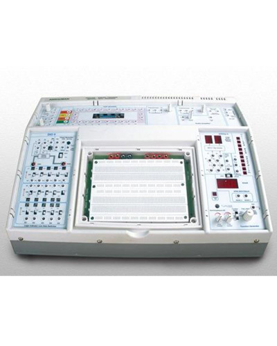
The Digital Trainer should be a modular course covering concepts, theory and applications for digital electronics training. It should be designed start the student with the basics of digital technology and goes onto advanced digital topics. All necessary equipment for digital trainer experiments such as multiple output power supply, clock generator, logic indicator, data switches, toggle switches, push buttons, pulsars and 7 segment displays should be installed on the base station. The base station should be able to work with modules required for experiments. A comprehensive operation manual and experiment manual are provided to be used together in doing the experiments. The digital trainer modules should have more 30 different types of ICs for student to explore.
Courseware:
The Digital Trainer should be included with operation manuals and experiment manuals which includes step-by-step chapters with theoretical information and practical student experiments. Each chapter must include student tests with an answer key.
The Digital Trainer should be able to conduct the following topics of experiments:
Technical Specifications:
a. Basic Digital Logic Training Module.
b. Advanced Digital Logic Training Module.
c. Modules:
The Digital Trainer should include experimental board modules that closely follow the courseware. The modules must be made of high quality epoxy coated fiber glass printed circuit board with the electronic components mounted on the surface. Each board should be printed with a clearly laid out silk screened schematic circuit diagram showing circuit construction and operation. The PCB modules must have all the components requested for the experiments mounted on to them. The modules should encompass of digital logic training modules and advanced digital logic training modules. The base station should also be able to facilitate digital application modules. Connections should be made by 2mm stackable test leads which are provided together with the modules.
d. Student Base Station
Serves as the platform for carrying out the student experiments. Provide for all the primary needs of the experiment modules.